Basic navigation
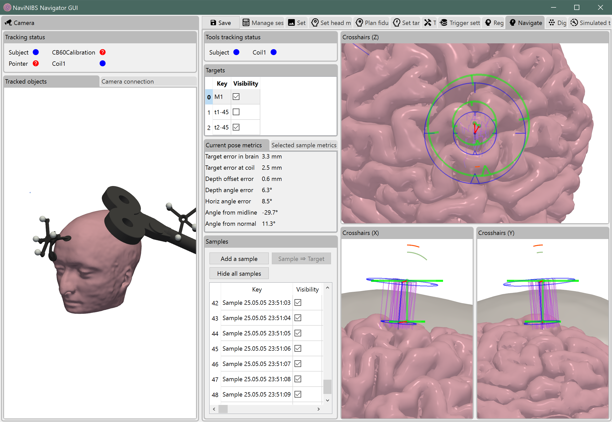
The Navigate tab is the main user interface that will be used during stimulation. It includes real-time view of coil position relative to a selected target, quantitative pose error metrics, and a history of recently sampled coil positions.
Tip
Drag the Camera tab to an edge of the main NaviNIBS window to see a real-time view of all tracked tools during navigation, as shown in screenshots here.
Targeting visualization
Blue crosshairs represent the current target position.
Green crosshairs represent the current coil position.
The larger diameter crosshair represents the target (or coil) at the depth of the coil’s bottom face (typically touching or just above the skin).
The smaller diameter crosshair represents the target at the depth of the target coordinate (typically near the cortical surface).
The triangular notch on each crosshair represents the direction of the coil’s handle, typically parallel (or antiparallel) with the direction of dominant current flow underneath the center of the figure-8 coil.
The red lines indicate the translational error between the target and the current coil position, at the depth of the target coordinate or of the intended coil position.
Orange arcs indicate angular error in the plane of the rendered view.
- Gray arcs (only shown in X and Y crosshairs views) show angular error from a locally estimated normal from the cortical surface to the skin.
Minimizing the gray arcs typically results in a coil orientation tangential to the scalp.
This measure is independent of the current target, and is particularly useful when exploring new stimulation locations away from a predefined target.
The angular error arcs (orange and gray) in the X and Y crosshairs views are magnified by a factor of 4 by default for greater visual contrast.
Visible targets are shown with blue depth-and-handle lines by default.
Visible samples are shown with purple depth-and-handle lines by default.
In the X and Y crosshairs views, the scalp surface is shown in a background layer in gray.
Pose metrics
- Target error in brain: distance from target in brain after projecting down to plane of cortical target.
Note: this determines depth of the target in the brain by finding closest point to the gm surf, so that we don’t need to assume that the target coordinate is already at the cortical surface.
Target error at coil: distance from target above scalp after projecting to the horizontal plane of the target’s coil.
Depth offset error: distance from targeted coil position along the target coil’s depth axis.
Depth angle error: angle between the target coil’s depth axis and the current coil’s depth axis.
Horiz angle error: angle from the target coil handle in the horizontal plane of the target’s coil.
- Angle from midline: angle between the coil handle and the midline of the head in the horizontal plane of the coil, with a modification for producing reasonable angles even extreme positions where a more strict angle from midline is not well defined / behaved.
Zero degrees is pointing straight back when the coil is near the top of the head, pointing straight down in the back of the head, straight up in the front of the head, and straight back when near the side of the head.
- Angle from normal: angle from the estimated normal (based on shortest distance between scalp and gray matter surfaces near the coil).
This measure can be overly sensitive to local variations in skin curvature, and should be interpreted with caution.
Samples
If triggers have been configured properly, a sample may be automatically recorded with every TMS pulse (or some more limited rate). Alternatively, samples can be manually recorded by clicking the Add a sample button.
A very large number of samples may slow down navigation rendering, so you may need to click Hide all samples occasionally to hide older samples from view during an experiment.
Manually selecting samples, even if previously hidden, will temporarily show those samples in the targeting visualizations.
A new target can be created from a sample by clicking the Sample -> Target button.