Coil calibration
In typical tracking setups, TMS coil optical trackers are not a predetermined position on a TMS coil. Therefore, a calibration is required to align the coordinate space of the observed optical tracker with the intended coordinate space of the coil itself.
Note
Calibration should be repeated whenever it is suspected that the coil tracker may have moved relative to the coil.
Using a calibration plate
NaviNIBS supports coil calibration using an additional tracked tool referred to as a calibration plate. This is a rigid body with a predefined origin and orientation, which can be held up to the coil and be used as a basis for estimating the spatial transform between the reported position of the tracker on the coil and the coil itself. We typically use custom 3D-printed jigs to facilitate accurate and repeatable alignment between the calibration plate and the coil.
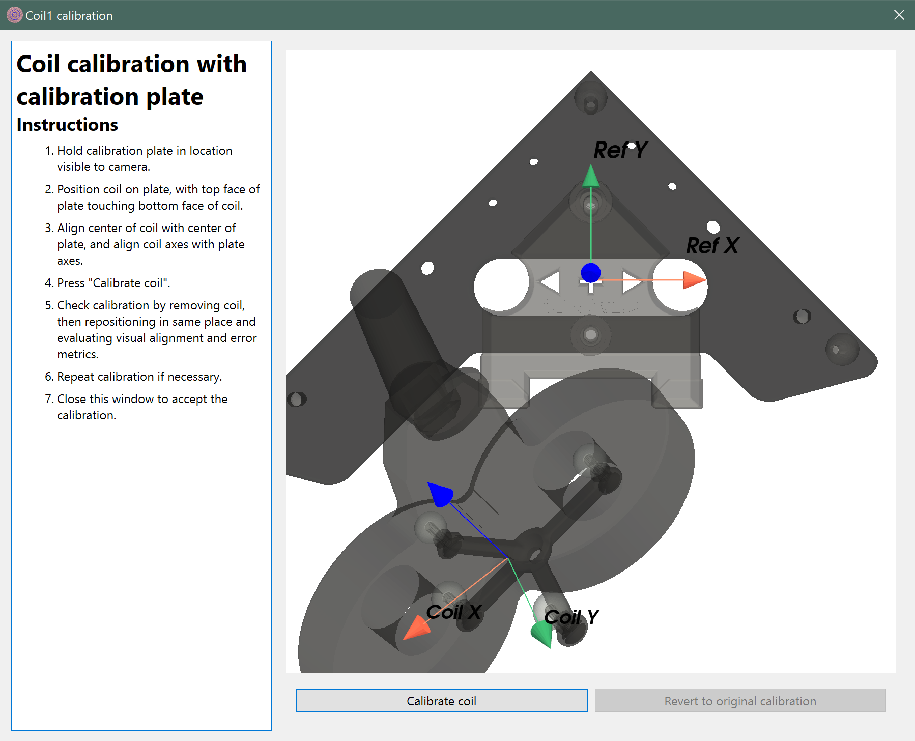 Before calibration
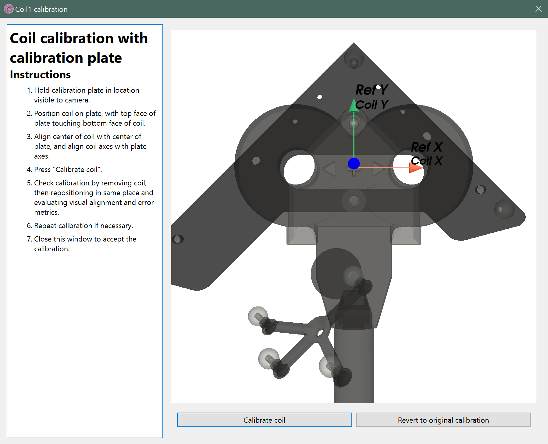 After calibration
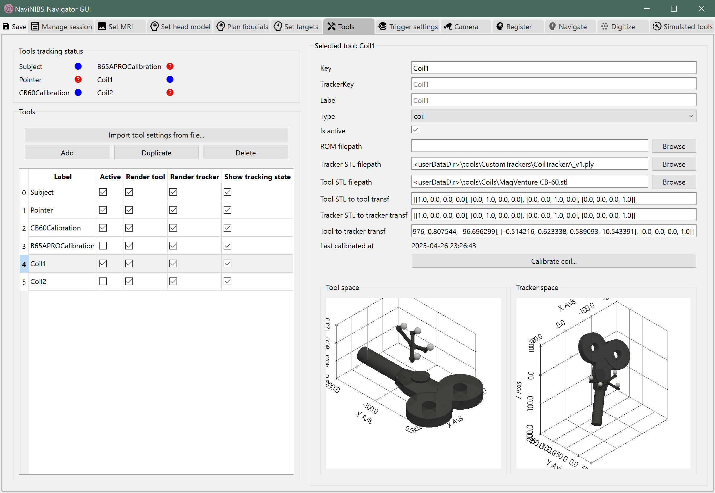 Tool panel after calibration
Coil calibration jigs
Using the OptiTrack CS-200 Calibration Square as a calibration plate with a known geometry, we have designed and 3D-printed a set of calibration jigs to be used with specific TMS coils. These jigs are designed to be held against the coil in a specific orientation, allowing the tracker to report its position relative to the coil’s coordinate system. See below for several examples.
These are attached to the calibration square using two 1/4-20 5/8” thumb screws (McMaster-Carr part number 98704A615).
Warning
These files are provided “as is” based on measurements of our own hardware. Please verify that the dimensions match your own hardware before using them for calibration.
MagVenture CB-60
MagVenture Cool B65 AP RO
Using a pointer for calibration
An alternative method of calibration is to use the tracked pointer to touch the coil at several planned points, and use this information to estimate the spatial transform between the reported position of the tracker on the coil and the coil itself. This does not require a calibration plate. NaviNIBS does not yet support this method of calibration, but it could be implemented in the future.
Coil coordinate system
Unfortunately, different software tools use different conventions for defining TMS coil coordinate systems. NaviNIBS uses the following, in relation to a typical figure of 8 coil with handle exiting in the plane of the figure-8 and perpendicular to the long axis of the figure-8, pointing down from the perspective of a person holding the coil in a typical stimulation position over a participant’s head:
origin: at the center of the figure-8, on the bottom face of the coil (closest to the scalp).
x axis: along the long axis of the figure-8, positive to the right.
y axis: along the short axis of the figure-8, positive pointing away from the coil handle (i.e. coil handle extends along the negative y-axis).
z axis: perpendicular to the coil face, positive pointing up away from the participant’s head.