Tool configuration
Each object with a pose (location and orientation) is referred to as a tool in NaviNIBs. Tools can include a subject head tracker, a pointer (or stylus), a TMS coil (and corresponding optical tracker), and more.
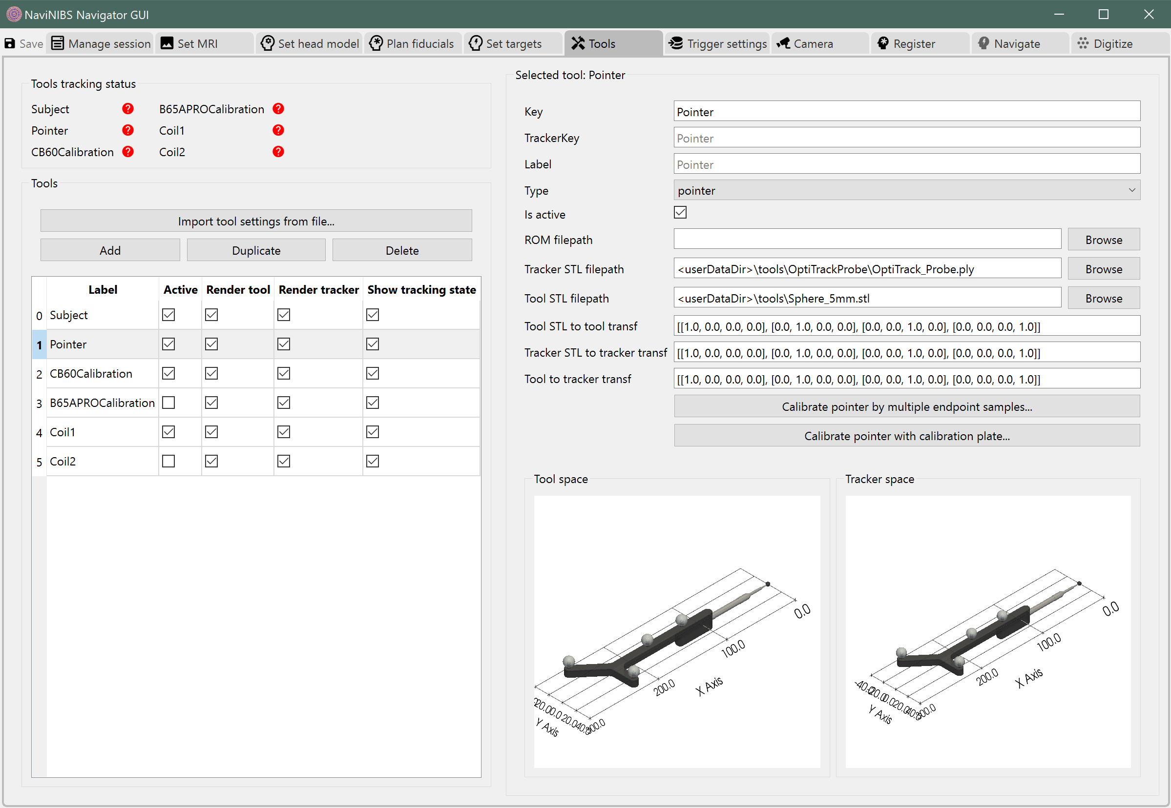
Each tool is defined by a set of specifications, which are visible in the Tools tab in NaviNIBS and are saved in the SessionConfig_Tools.json file within a session directory.
The most important specifications for a tool are a unique key, a type (usedFor), and a path to at least one surface mesh (trackerStlFilepath or toolStlFilepath) for visualization. Other specifications can be left unspecified; see detailed list of tool specifications below for more information.
Typically you should define your tools used for a study once, then import that same tool settings file for each session (or build it into a session template). See an example below. During a typical session, the only reasons to visit the Tools tab would be to calibrate a TMS coil tracker or to switch between multiple coils.
Detailed list of tool specifications
-
Tool._key:
K
-
Tool._key:
-
Tool._trackerKey:
Optional[str] Optional key to match up to tracking data. If not specified,
keywill be used instead.
-
Tool._trackerKey:
-
Tool._label:
Optional[str] Optional “nice” label for display. If not specified,
keywill be used instead. Label does not need to be unique, but could be confusing in some GUI displays if multiple tools with the same label are shown.
-
Tool._label:
-
Tool._isActive:
bool Whether to actively use for tracking/pointing
-
Tool._isActive:
-
Tool._doRenderTool:
bool Whether to show tool in camera view, etc. To actually render, a valid pose and mesh must be available.
-
Tool._doRenderTool:
-
Tool._doShowTrackingState:
bool Whether to include this tool in tracking status widget(s). To actually show, must not also be excluded by other hide filters on the widget.
-
Tool._doShowTrackingState:
-
Tool._romFilepath:
Optional[str] Path to a .rom file describing optical marker positions on a rigid body tracker, as used by NDI Polaris systems.
-
Tool._romFilepath:
-
Tool._trackerStlFilepath:
Optional[str] Path to a surface mesh file (e.g. .stl, .ply) for visualization of the tracker.
-
Tool._trackerStlFilepath:
-
Tool._toolStlFilepath:
Optional[str] Path to a surface mesh file (e.g. .stl, .ply) for visualization of the tool.
-
Tool._toolStlFilepath:
-
Tool._filepathsRelTo:
str Can be one of:
'<install>': relative to NaviNIBS install dir'<userDataDir>': relative to user data dir'<session>': relative to session fileabsolute path
-
Tool._filepathsRelTo:
-
Tool._toolToTrackerTransf:
ndarray] Used for aligning actual tool position to Polaris-reported tracker position (e.g. actual coil to coil tracker, or actual pointer to uncalibrated pointer tracker)
-
Tool._toolToTrackerTransf:
-
Tool._toolStlToToolTransf:
ndarray] Used for visualization of tool surface mesh only; can be used to align mesh with actual tool orientation
-
Tool._toolStlToToolTransf:
-
Tool._trackerStlToTrackerTransf:
ndarray]
-
Tool._trackerStlToTrackerTransf:
-
Tool._toolColor:
str | None
-
Tool._toolColor:
-
Tool._trackerColor:
str | None Note: some surf file formats (e.g. .ply) allow specifying color of elements within the file; if color is None here and colors are available in the surf file, those colors will be used.
-
Tool._trackerColor:
-
Tool._toolOpacity:
float | None
-
Tool._toolOpacity:
-
Tool._trackerOpacity:
float | None
-
Tool._trackerOpacity:
-
Tool._initialTrackerPose:
ndarray] For defining initial pose of tool, e.g. for tools that never get a camera-reported position, or for a default (simulated) position when a camera is not connected.
-
Tool._initialTrackerPose:
-
Tool._initialTrackerPoseRelativeTo:
str
-
Tool._initialTrackerPoseRelativeTo:
Most of these can be left unspecified, as they have reasonable default values.
Example SessionConfig_Tools.json
[{
  "key": "Subject",
  "trackerStlFilepath": "tools\\CustomTrackers\\SubjectTracker_v1.ply",
  "usedFor": "subject"
}, {
  "key": "Pointer",
  "trackerStlFilepath": "tools\\OptiTrackProbe\\OptiTrack_Probe.ply",
  "toolStlFilepath": "tools\\Sphere_5mm.stl",
  "usedFor": "pointer"
}, {
  "key": "CB60Calibration",
  "toolStlFilepath": "tools\\CoilCalibrationJigs\\CB60CalibrationJig1p0.ply",
  "toolToTrackerTransf": [
    [1.0, 0.0, 0.0, 0.0],
    [0.0, 1.0, 0.0, -90.259],
    [0.0, 0.0, 1.0, 0.0],
    [0.0, 0.0, 0.0, 1.0]
  ],
  "usedFor": "calibration"
}, {
  "key": "B65APROCalibration",
  "isActive": false,
  "toolStlFilepath": "tools\\CoilCalibrationJigs\\CoolB65APROCalibrationJig1p1.ply",
  "toolToTrackerTransf": [
    [1.0, 0.0, 0.0, 0.0],
    [0.0, 1.0, 0.0, -97.459],
    [0.0, 0.0, 1.0, 0.0],
    [0.0, 0.0, 0.0, 1.0]
  ],
  "usedFor": "calibration"
}, {
  "key": "Coil1",
  "trackerStlFilepath": "tools\\CustomTrackers\\CoilTrackerA_v1.ply",
  "toolStlFilepath": "tools\\Coils\\MagVenture CB-60.stl",
  "usedFor": "coil"
}, {
  "key": "Coil2",
  "isActive": false,
  "trackerStlFilepath": "tools\\CustomTrackers\\CoilTrackerB_v1.ply",
  "toolStlFilepath": "tools\\Coils\\MagVenture Cool B65 AP RO.stl",
  "usedFor": "coil"
}]
Tool 3D models
Some tracked tools from other neuronavigation systems can be used in NaviNIBS, or new calibration tools can be purchased (e.g. from OptiTrack or NDI). This is recommended for high-precision tools like pointers and calibration plates.
See Coil calibration jigs for examples of 3D-printed coil calibration jigs and related coil geometries.
Tools with less stringent geometry requirements can also be 3D-printed and combined with infrared-reflective spheres to create custom tracked tools. For example, the subject and coil trackers below can be 3D printed, combined with M4 threaded reflective markers, M4 nylon flat head screws (e.g. McMaster-Carr part number 92929A255), M4 nylon nuts (e.g. McMaster-Carr part number 93800A500), and M6 flat head screws (McMaster-Carr part number 91294A237) to connect the subject tracker top to tripod base.